BMW E39 Gauge Cluster
Three ESP32 programs I wrote to try to drive the rev counter of an old BMW 5 Series instrument cluster over CAN bus, with no engine attached. I never got my own code to move a needle, though the cluster's built-in test did.
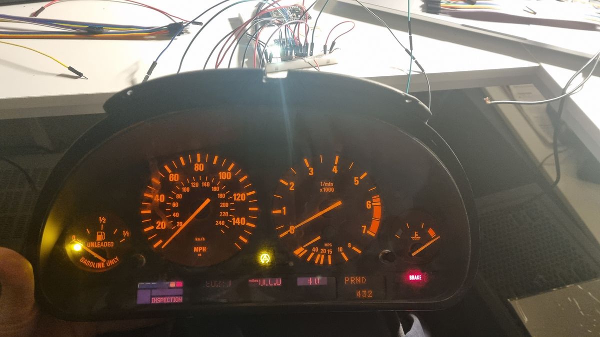
I started this about a year and a half ago because I liked how the dashboard of an old BMW looked: the lights, the little screen, the dials. I wanted one on my desk as a sort of living piece of art, something that could show what a game was doing, or just move around when I felt like it. I got hold of an instrument cluster and had a go at making it do things.
It didn't get that far. I put it aside, came back to it a year later, fixed a few problems and worked out which pins to use for the CAN bus, the network I'll explain in a moment. What I never worked out was how to get the Arduino code talking to the cluster so I could control it myself. I did see the cluster light up and its needles move, but that was the cluster running its own built-in test program, not anything I wrote. Then I had to move, and the cluster went in the bin. I think I would have figured it out eventually.
Here is what I was trying to do. Behind the steering wheel of a BMW E39, the 5 Series built from the mid-1990s to 2003, sits the instrument cluster: the speedometer, the rev counter, the warning lights. Most of what it shows arrives as messages from the car's other computers, not from sensors wired to the cluster. The engine computer works out how fast the engine is turning and sends the cluster a short message about it, many times a second, over a shared two-wire network called a CAN bus. The needle moves because a message says it should.
So in theory the cluster follows anything that sends the right message, and that was the whole idea. A small board called an ESP32 pretends to be the engine computer and tells the cluster that the engine is turning at some speed. The cluster is a bit like someone reading from a teleprompter: it says whatever turns up, and has no idea whether there is a real engine behind it.
I wrote three small programs for it. The first only listens to the bus and prints whatever it hears. The second is a checklist that tests whether the connection is alive at all and tells you what each failure would mean. The third is the one meant to make the needle move: it sends the engine-speed message and sweeps the speed from 0 up to 6000 revolutions a minute and back down, 100 at a time, ten steps a second. One round trip takes 12 seconds.
It only goes as far as the rev counter. The temperature values it sends are fixed placeholders, nothing feeds it a real engine or a game, and the layout of the messages is not mine: I took it from an existing project for the cluster of the BMW 3 Series that came after, and I assumed the two clusters speak the same language. I never found out whether that holds, because I never got my own messages to do anything.
One thing worth knowing is that the sweep program keeps sending whether or not a dashboard is plugged in. The numbers scrolling past on my laptop would look the same either way, which is why the checklist listens and checks the wiring as well.
What's next. Nothing, for now. The cluster is gone and the project has stalled. If I ever did it again I would start with the part that stopped me, getting the code to talk to the cluster, and only then add the other needles and a real source of numbers, like a driving game.
What I was after
I started this about a year and a half ago because I liked the way an old BMW dash looks, with its lights, small screen and dials, and I wanted one on my desk as a living piece of art that could react to games or just do its own thing. I set it aside, came back a year later, fixed some issues and worked out the pins for the CAN bus. The part I never solved was how the Arduino code should talk to the cluster to control it. I did see it light up and move its needles when I ran the cluster's own built-in test program, but none of my code ever drove it. Then I had to move and threw the cluster away, so the project is stalled. The code below is what I had when it stopped.
The technical goal was to move the needles of an E39 instrument cluster from an ESP32. Most of what the cluster shows arrives over CAN from other control units. The rev counter is fed by the engine computer, the DME, so the job is to impersonate the DME. The rev counter comes first because it is the only value in my code that actually changes. Everything below describes what the programs are written to do. None of it was ever seen to move a needle.
How it works
All three programs use the ESP32's built-in CAN controller through the ESP-IDF twai driver, at 500 kbit/s, with TX on GPIO21 and RX on GPIO22. Those pins go to an MCP2551 transceiver, which is what sits on the bus.
What is CAN bus?
A two-wire network that cars use to let their computers talk. Nothing is addressed to a particular device. Each message carries an ID that says what it is about (engine speed, say) and up to 8 bytes of data, and anyone who cares about that ID reads it. A cluster is simply a listener for the IDs it displays.
What does the MCP2551 do?
The ESP32 has a CAN controller, but its pins are ordinary logic signals. A transceiver converts them to and from the differential voltage the two bus wires actually carry. Without one, the controller cannot talk to a real bus.
The sniffer is the simplest. It runs in listen-only mode, prints every frame with its ID and bytes, and reports the driver's error counters every five seconds. Its start-up message says that if nothing shows up after ten seconds, the wiring is wrong. The diagnostic, covered further down, is a longer version of the same idea. The sweep is the real attempt.
It takes its frame format from an existing project for the E46 cluster, which is not mine, and assumes that E39, E46 and E38 clusters share the protocol. It sends four frames and steps the engine speed from 0 to 6000 rpm and back in steps of 100, one step every 100 ms. That is a 12-second round trip.
What the sweep sends
| Frame | Every | Content |
|---|---|---|
| 0x316 DME1 | 10 ms | Engine speed in bytes 2 and 3, plus fixed status and torque bytes |
| 0x329 DME2 | 100 ms | Fixed coolant temperature, throttle and engine-running bytes |
| 0x545 DME4 | 100 ms | No warning lights, fixed oil temperature byte |
| 0x153 ASC1 | 100 ms | All zeros, to clear the ABS and traction lights |
That is 130 frames a second. A standard frame with 8 data bytes is about 111 bits on the wire, so the sweep fills roughly 3 percent of a 500 kbit/s bus. That is counted from the frame length, before bit stuffing, not measured on the bus. Each send waits at most 5 ms to be queued, and if the controller has gone bus-off the sketch restarts it.
The engine speed is encoded as rpm × 6.4, as a 16-bit value, low byte first. The diagnostic sketch's test frame carries 0x4B00, which is 19200 / 6.4, so 3000 rpm.
What do 16-bit and low byte first mean?
A byte holds 0 to 255, which is too small for an engine speed, so the number is split across two bytes. Low byte first means the least significant half goes out in byte 2 and the most significant half in byte 3. For 19200, which is 0x4B00, byte 2 is 0x00 and byte 3 is 0x4B. The largest 16-bit value, 65535, would be about 10,000 rpm, so there is plenty of room above 6000.
uint16_t rpmVal = (uint16_t)(rpm * 6.4);
uint8_t rpmLSB = rpmVal & 0xFF;
uint8_t rpmMSB = (rpmVal >> 8) & 0xFF;
Slide the speed below to see the two bytes and the whole frame it produces. Where motion is allowed, a sweep button plays the loop from the code: 100 rpm every 100 ms, up to 6000 and back. The dial is a toy, not the cluster. The numbers underneath are computed with the same formula as the code.
Checking the link
The diagnostic runs four tests in a single boot. Tests 2 to 4 are each paired with a printed reading of what the result would mean, so the output tells you where to look. Each box in the diagram below matches one step in the list.
What do listen-only and no-ACK mean?
On CAN, a frame is only counted as delivered if at least one other device on the bus acknowledges it, so a lone transmitter keeps retrying the same frame and never sees it delivered. Listen-only mode never transmits, which makes it safe for looking. No-ACK mode transmits without needing anyone to acknowledge, which lets a sender run on an empty bus. Both are modes of the ESP32's driver, and the sweep uses the second.
Limits
It only drives the rev counter. The coolant byte in DME2 and the oil temperature byte in DME4 are both fixed at 0xAB, so treat both temperatures as placeholders rather than data. There is nothing for the other gauges, no input from a real engine or a simulator, and no enclosure.
The sweep sends in no-ACK mode, so it runs whether or not a cluster is attached. The serial monitor printing RPM: 3000 proves nothing about the cluster, which is what the diagnostic is for.
The frame layout is borrowed. The assumption that E39, E46 and E38 clusters share the protocol comes with it, and I never confirmed it on the E39, because none of my code got the cluster to respond. The only movement I saw came from the cluster's built-in test.
What's next
Nothing, at the moment. I gave up on it when I moved, and the cluster is gone. I still think I would have worked it out and ended up using it for projects and games. What was never done: getting the code to control the cluster at all, then the other needles, checked scaling for the temperature bytes, a live data source such as a game, and a box to put it in. If I picked it up again I would start with the first of those.
- Stack
- ESP32, Arduino framework, ESP-IDF twai CAN driver, MCP2551 transceiver
- Credit
- Frame format borrowed from an existing project for the BMW E46 cluster
- Timeline
- Started about a year and a half ago, put aside, picked up again a year later
- Status
- Prototype
- Now
- Stalled; the hardware is gone
- Code
- Not public