PicoTalon
A 3D-printed RC plane, assembled and waiting for its electronics, plus a computer model I use to check decisions before it flies.
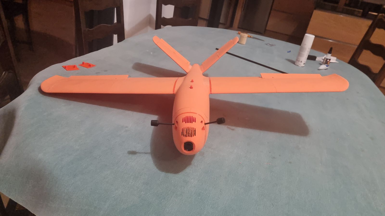
What I like most about 3D printing is the material itself: how different infills feel in your hands, how strong they turn out to be, what kind of force each one holds against, and the way the printer lays them down. A plane is a good excuse to use all of that. I wanted to build one that actually flies before trying anything fancier. It is a small hand-launched plane with a 90 cm wingspan, a propeller at the back and a camera in the nose, so you fly it by looking through goggles. The design is the Pico Talon by Flightory. I bought the design files, so it is not my design, and I don't share the files themselves.
Every part that can be printed is printed. Most of it is in a filament that foams as it melts, so the plastic ends up full of tiny bubbles and weighs almost nothing; the parts that carry load are in a tougher plastic. The photo below is from before I put it together. With the battery in and no other electronics, the assembled plane weighs 400 g. It is still a work in progress: I am waiting for the electronics to arrive, meaning the motor, the speed controller (the small box that feeds power to the motor), the little motors that move the control surfaces, the flight controller (the small computer that steers) and the camera gear. After that comes the first test flight. It has not flown.
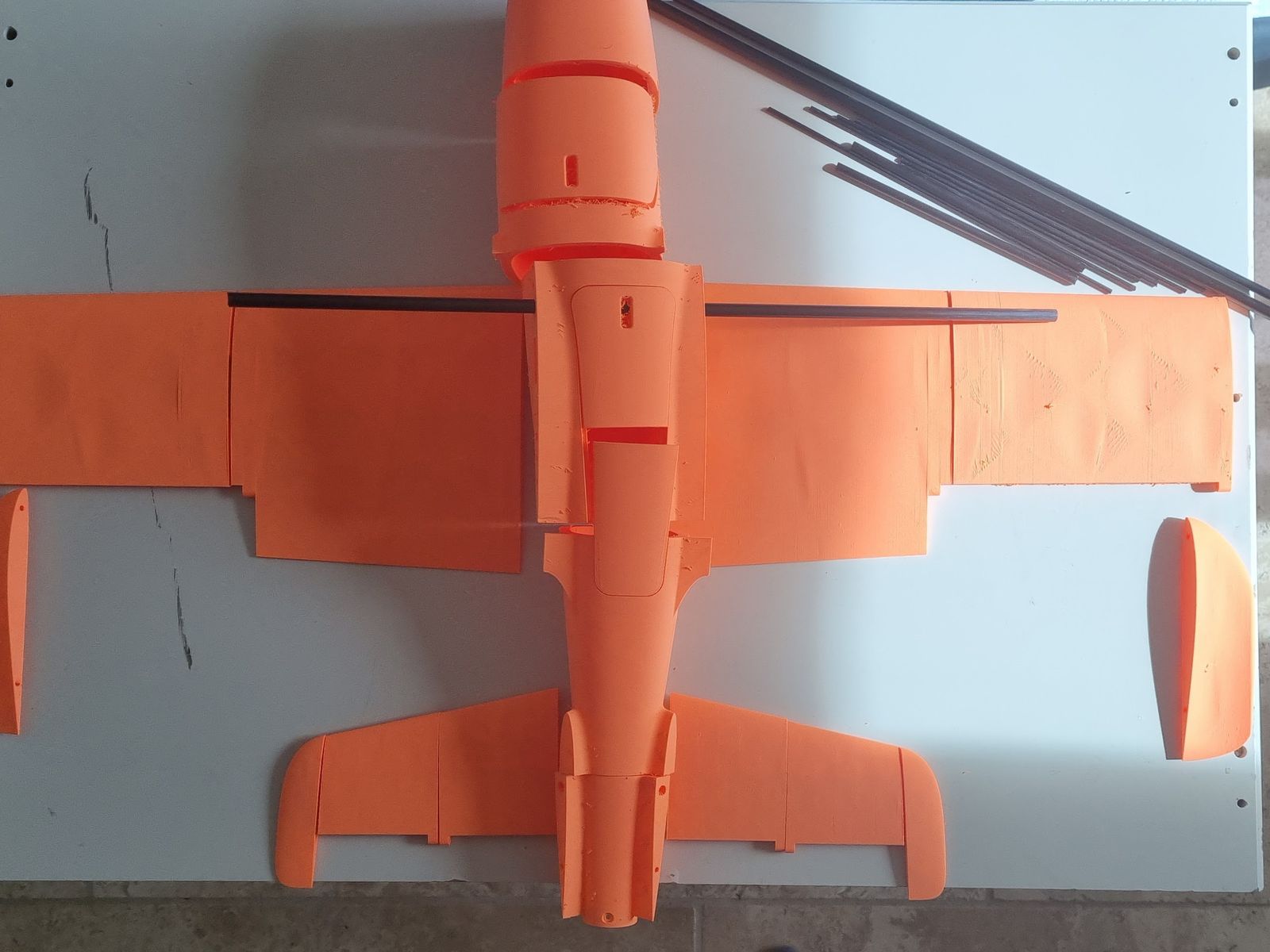
I have not tested the strength properly, but I did lean on a few spare, broken and misprinted parts, nothing drastic. They are a lot stronger than I expected. Even a single layer with the sparsest infill holds up really well.
While it was printing I built a computer model of the plane from the shapes of the parts. Think of it as a very serious paper-plane test: it says where the plane balances, how slowly it can fly before it drops, and how long a battery should last. Three things it caught are in the diagram below.
Everything the model says is a prediction. The only thing I have measured on the real plane is its weight; nothing has been measured in the air. The model says a battery should last about 40 minutes of slow, steady flying, and probably 25 to 30 minutes with climbs, turns and wind. I would treat that as optimistic until it flies.
Not everything worked. I also tried simulating the airflow around the whole plane on my graphics card. Every time I made the grid finer the answers shifted again, and they stayed far from the simple model, so I threw those numbers out. And the fifth section of the body failed twice on the printer, with strings of plastic smeared inside, before the third try came out clean.
What's next
The electronics arrive and go in, and I weigh the plane again with everything on board. Then I test the motor on the bench with the plane held down, then I practise on a flight simulator, then the first real flight. That flight is what will show me how wrong the model is. In France a plane with a camera needs me to register as an operator and pass a short online exam first, and flying with goggles needs a second person watching the plane the whole time. I will also check the airspace around wherever I fly.
What I wanted
The part of printing I enjoy most is the material itself: how different infills feel, how strong they turn out to be, what kind of force each one holds against, and how the printer lays them down. A plane is a good place to use all of that. The goal is one 3D-printed plane flying, before anything fancier. The longer idea, several aircraft working together without a ground link, is parked on purpose. This one is a hand-launched pusher with FPV video from a DJI O4 Air Unit Pro, an ExpressLRS receiver, and a TBS Lucid H7 Wing flight controller, which I'll most likely run ArduPilot on.
The airframe is the Pico Talon by Flightory: 905 mm wingspan, 640 mm long. It is not my design. I bought the file pack, so I am not sharing its STLs, plans or renders. The photos, diagrams and plots here are mine. Every part that can be printed is printed and it is assembled; I am only waiting for the electronics to arrive. With the battery in and no other electronics it weighs 400 g.
Almost every part is Prusament PLA Lightweight, a foaming filament, printed on a Prusa CORE One+. The slicer estimates all the LW-PLA parts at about 260 g together. The parts that carry load are Prusament PETG.
What is LW-PLA?
A PLA filament with a foaming agent in it. When it melts in the nozzle it swells, so a printed wall is mostly tiny bubbles and much lighter than ordinary PLA. Because it swells, the slicer has to push out less of it (an extrusion multiplier of about 0.45 here), and it is fussy about stringing.
How it is built
I slice the LW-PLA parts one at a time in PrusaSlicer 2.9.6, starting from Prusa's own settings for the filament: 230 °C, extrusion multiplier about 0.45, one wall, sparse infill. Flightory's manual calls for a lattice infill that PrusaSlicer doesn't have, so I chose the wing infill from slicer estimates on one panel (adaptive cubic at 3%: 24.9 g, about 4 hours). All four wing panels were printed with it. None has flown.
Orientation matters for a part with thin walls, so I check each one against the manual's pictures by slicing the first layers. Eyeballing a render got one wrong: the FUS 2 part as supplied has about 1550 mm² of overhang, and 64 mm² flipped, which is how the manual shows it.
The 21 PETG pieces are laid out on plates (two, plus a third that redoes the wing roots and adds a spare set of locks). The first two come to about 82 g by the slicer, and the single-part slices added up to about 83 g.
How strong the parts are
I have not run a proper test. I put spare, broken and misprinted parts under load, nothing drastic, and they are surprisingly strong. Even a single layer with minimal infill is still really good. I find it hard not to enjoy this: how different the infills feel, how much each one can take, which direction of force it takes it from, and how they are put down line by line. These were informal hand tests, so I have no numbers.
A model of the plane
While the parts were printing I built scripts that rebuild the plane from the CAD meshes, so I could ask questions before anything was wired. Where does the centre of gravity land, is it stable, what does the powertrain draw. The chain is in the diagram above: a 1:1 assembly checked against Flightory's 640 mm length, a mass budget, a vortex-lattice model with a fuselage term, then a motor, speed controller, battery and propeller model.
What is a vortex-lattice model?
It covers the wing and tail with a grid of small panels, each carrying a vortex, and solves for the lift pattern that makes the air flow along the surface. It is fast and good at lift and balance, but it ignores thickness and friction. So I feed each wing strip's result to NeuralFoil, a network trained on XFoil results, to add the drag and the point where each section stalls.
What the model says
| Quantity | Value |
|---|---|
| Neutral point | X 295 mm (range 285 to 297) |
| Static margin at the manual's CG | 11.6% MAC (plausible 6 to 13%) |
| Stall speed | 31 km/h (33 with a more cautious CLmax) |
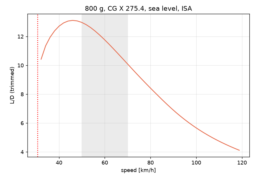
| Best L/D, trimmed | 13.1 at 46 km/h (12.0 at 43.5 with extra drag) |
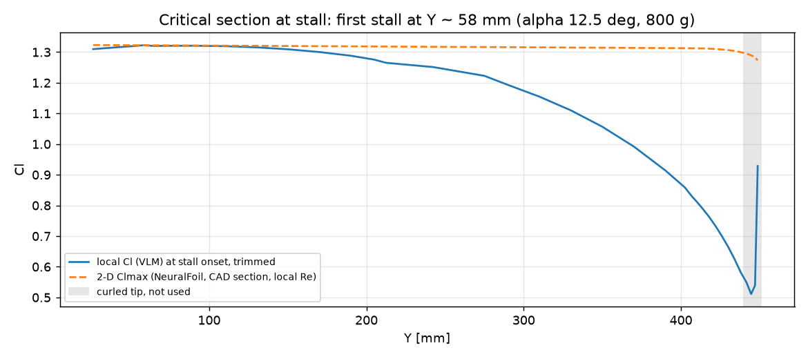
| First stall | Wing root; the tips keep a large margin |
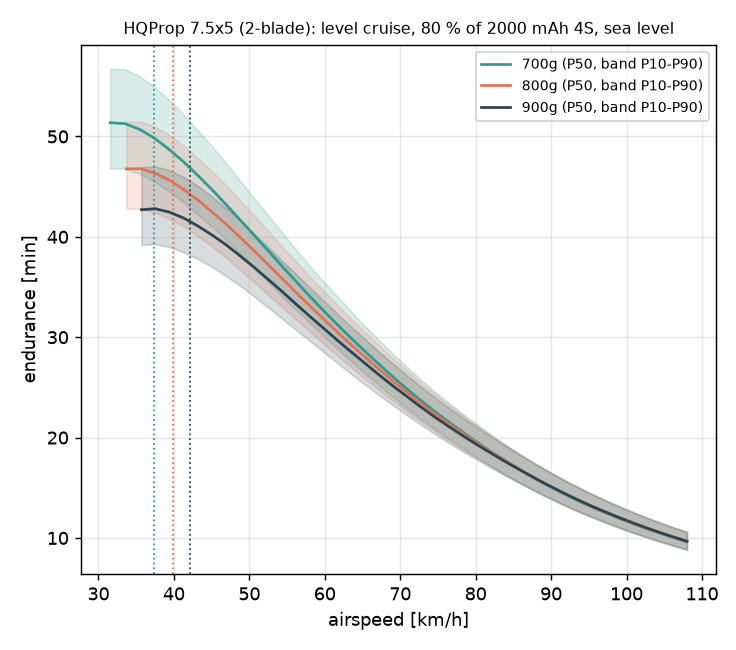
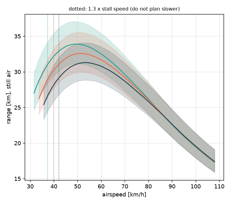
| Cruise endurance, 80% of the pack | 41 to 49 min at about 41 km/h (about the slowest speed I allow, roughly 1.3 × stall; in practice I would fly about 45 km/h and lose only about 2 min), 33 to 39 min at 55 km/h |
| Same, with climbs, turns and wind | about 24 to 31 min at 55 km/h. A planning estimate that assumes 25 to 35% extra energy |
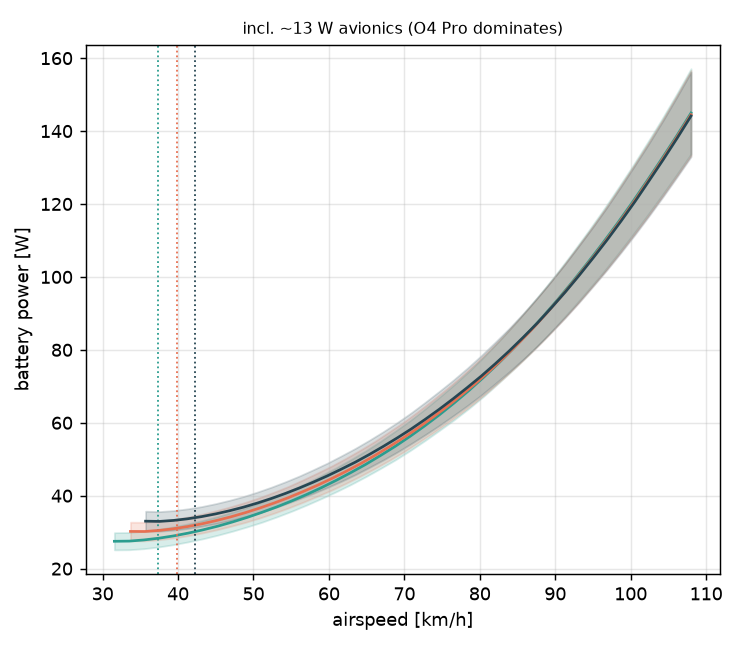
Endurance rows: HQProp 7.5x5. The range is P10 to P90 of 1500 runs with my uncertain inputs varied, so it shows how much my guesses matter, not how much flights will vary. The propeller data is the biggest guess: it is computed data, calibrated on a different prop. None of these numbers is measured on the real plane.
What do centre of gravity and static margin mean?
The centre of gravity (CG) is where the plane balances. The neutral point is the spot where its own pitch stiffness cancels out. The static margin is the gap between the two, as a fraction of the wing's average chord (MAC). A bigger gap is calmer and a little sluggish. A CG at or behind the neutral point means the plane is unstable and would pitch away from you.
The mass budget is 824 g, and I made it before weighing anything. The bare airframe with the battery now weighs 400 g on the scale, lighter than the budget has for the same parts, so the budget is probably too high. I will redo it from real weights once the electronics are in, and the 700 g curves below show what a lighter plane does. In the other direction, at 900 g the same model gives a stall of about 32 km/h and 38 to 45 min best endurance.
I compared the aerodynamics with the polars in Flightory's manual. My lift at zero angle of attack and my lift slope agree with those polars to within 2%. That checks my model against their calculation, not against a plane. Their curves look like a wing-and-tail calculation without the fuselage (they don't say what it contained). In my model the fuselage costs roughly 20% of L/D and about 6% MAC of static margin.
It stalls at the wing root first, next to the fuselage, and the tips keep a large margin, so the stall should be gentle.
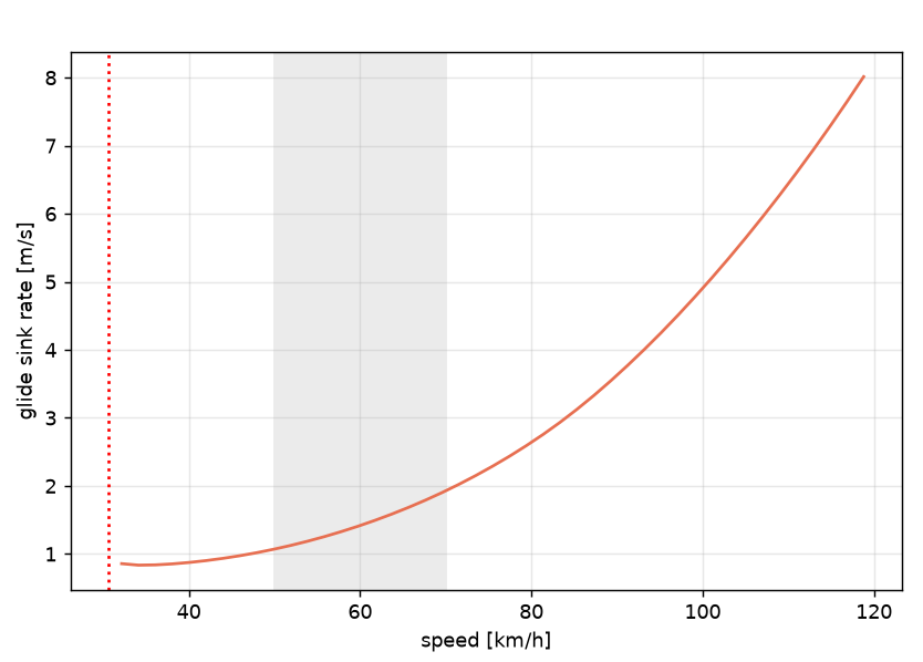
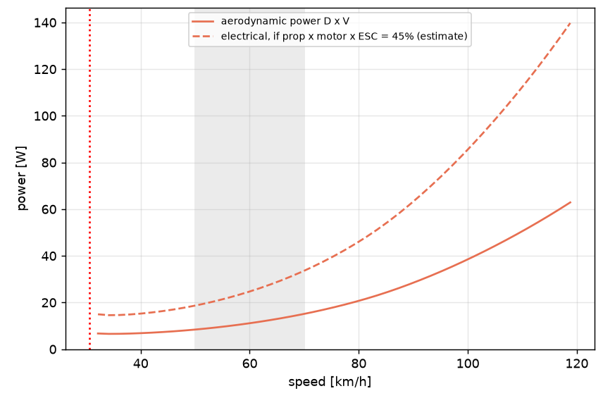
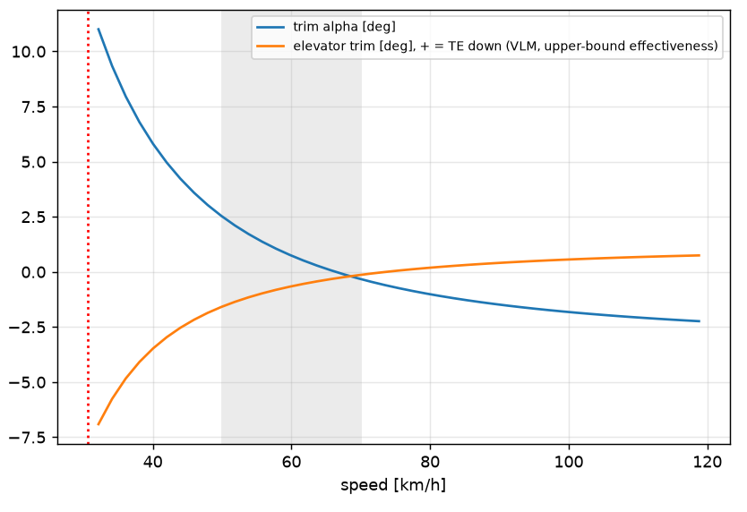
In cruise the battery supplies about 40 W, and about 13 W of that is avionics, mostly the O4 Pro. Without it, cruise endurance would be about 25% longer. DJI doesn't publish the O4 Pro's power draw. I use 9 W, with 7.5 to 10.5 W as the range. The 10.5 comes from one third-party page and I haven't measured any of it, so treat the 13 W and the 25% as soft.
What is a Monte Carlo band?
I ran the endurance calculation 1500 times, each time drawing every uncertain input (prop efficiency, avionics power, drag, battery capacity) at random from a plausible range. P10 to P90 is the middle 80% of those runs. It shows how much my guesses matter. It says nothing about how the plane will really do.
What didn't work
The fifth fuselage section failed twice. First with retraction off, which had worked on simpler parts: ooze piled up. Then with retraction, wipe and avoid-crossing, which left a mess inside. G-code measurements showed the trade. The settings that worked on FUS 2 and 3 put about 12 m of travel across the hollow bore, and avoiding that made the nozzle follow the walls with 4355 retractions, smearing strings inside. The third attempt went back to the FUS 2 and 3 settings and came out fine.
The stock nose can't carry the camera. The O4 lens would sit about 12 mm behind a 16 mm window, so only about 67 degrees of its 155 degree view gets out. It needed a different front, one that loads from the rear, leaves the cables plugged in and puts the antennas left and right. Revision 3.3 was printed, and when I checked it, a slot stopped short, so the camera could not go in. It and 3.4 were replaced by a rear-loading nose (RL1e) that takes the whole unit from behind. That nose is printed and on the plane, and it works. The camera has not run in it yet, so cooling is untested, and the antennas end up about 16 mm from the video transmitter, where DJI asks for 50 mm.
The airflow simulation is no use. I ran the whole plane through FluidX3D, a lattice-Boltzmann solver, on my GPU, at 15 m/s. It is not grid-converged: the answers keep changing as the cells get smaller, and they stay far from the lifting-surface model. Drag comes out four to six times higher than my model gives. Pick a cell size below to see it. I leave those numbers out of everything else here.
The mass budget is soft. It was built from slicer weights, shop weights and guesses, it sits well above what the scale says for the airframe, and its PETG weights are lower than the slicer's. An earlier budget put the CG at X 296.6 mm, behind the neutral point, which would be unstable. Moving the battery forward fixed it on paper (X 275.4 mm now).
The powertrain is oversized for its speed controller. On paper the 7.5x5 propeller at full throttle draws 56 to 61 A from the battery, against a 40 A controller and a motor rated 36 A peak. The model says to cap throttle near 72%. Cruise only needs 25 to 40%, so the cap costs nothing in normal flying.
What is unfinished
Every part that can be printed is printed, so what is left is the electronics, and they have not arrived yet. When they do, the motor, speed controller, servos, flight controller and FPV gear go in. I will weigh the finished plane and redo the mass budget, since 824 g is an estimate and the airframe came in at 400 g with the battery.
Before the first power-up I will do a bench thrust and current check with the plane restrained and the propeller on. Before the first flight, simulator practice. The first flight log will tell me how wrong the model is, and I will fit it to that.
In France a plane with a camera needs operator registration and the online open-category exam. Flying in goggles needs a second person who keeps the plane in sight, and 800 g or more adds aircraft registration and a signalling beacon, which is one more reason to weigh it with everything on board. I will check airspace and local restrictions before any outdoor flight.
- Design
- Flightory Pico Talon, purchased; not mine
- Mine
- The print setup, the slicing checks, the mass budget and the model of the plane
- Stack
- Prusa CORE One+, PrusaSlicer, LW-PLA and PETG; Python, AeroSandbox, NeuralFoil, FluidX3D (lattice-Boltzmann solver, free for non-commercial use), APC and UIUC propeller data
- Stage
- Fully printed and assembled; waiting for the electronics to arrive; not flown
- Weight
- 400 g with the battery and no other electronics
- Status
- In progress
- Code
- Not public